Home Station 23.1 Assembly
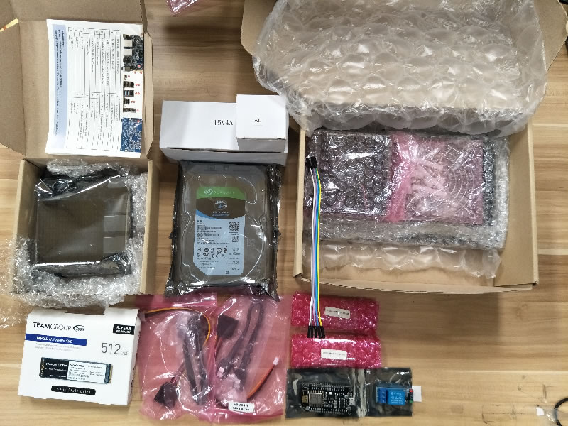
Please place all components on an anti static mat and ground yourself, e.g: using an anti static wrist strap
1.The Case
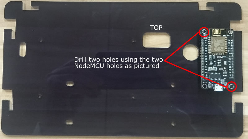
Two M4 size holes are needed to mount the NodeMCU and Relay. Remove the protective plastic coating before drilling.
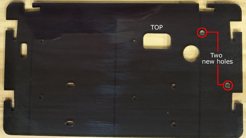
Two new holes drilled.
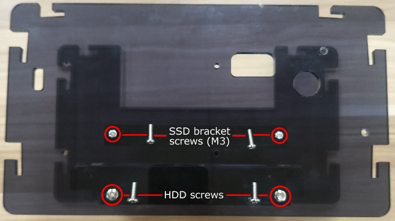
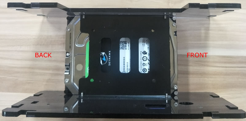
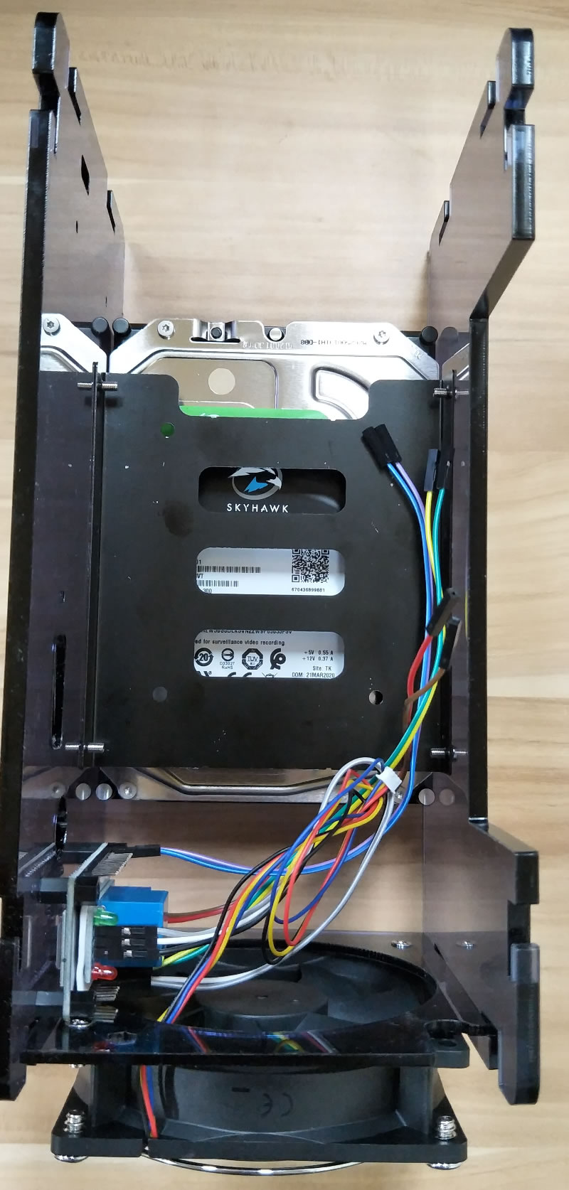
2.Hard Drive and 3.5" SSD bracket
Using two screws on each side to install the HDD and 3.5" SSD bracket. The four screws for the 3.5" SSD bracket are M3 type, smaller and shorter than the four screws for the HDD.
Please make sure the two acrylic sides have the same orientation.
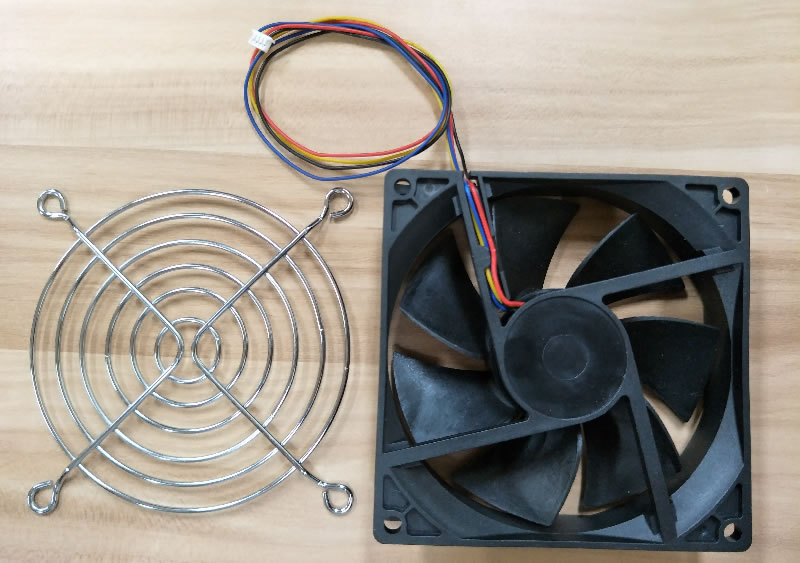
3.The Fan
The fan grill is installed on this side of the fan.
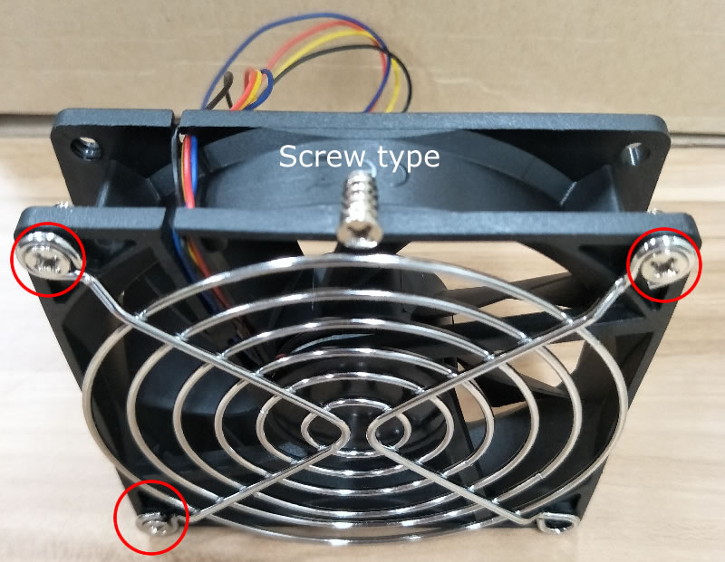
Using three screws, attached the grill to the fan.
Using two screws, attached the fan acrylic backing to the fan. Remove the protective plastic coating before attaching it to the fan and pay attention to the orientation.
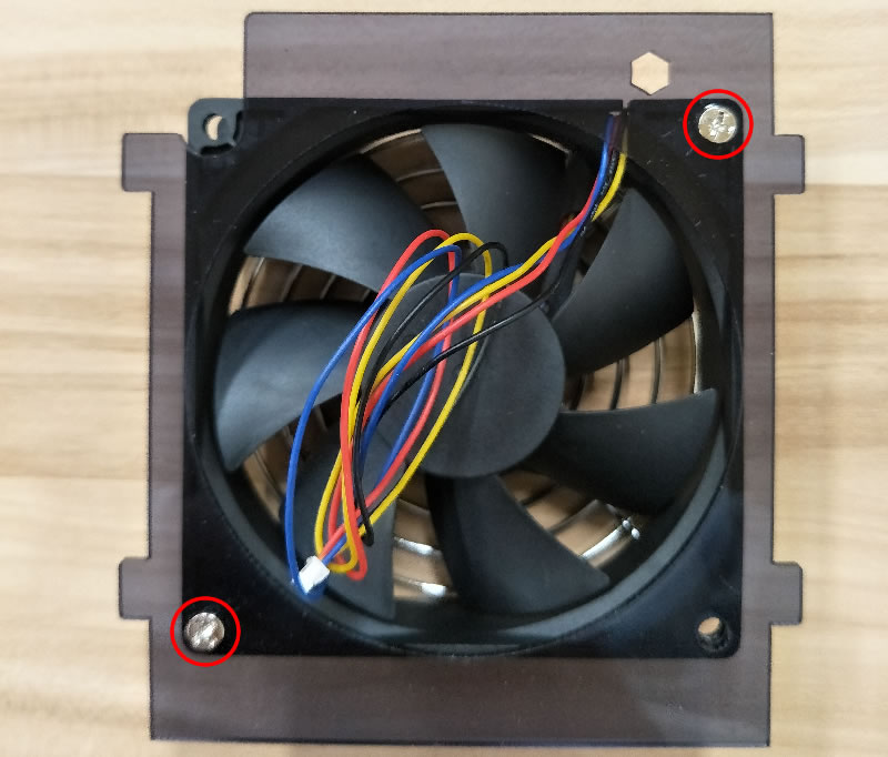
Slide the fan backing so it is securely attached to the front side of the long acrylic sheets used by the HDD and 3.5" SSD bracket.
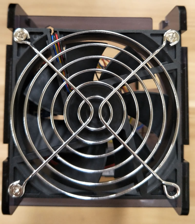
This is the top view.
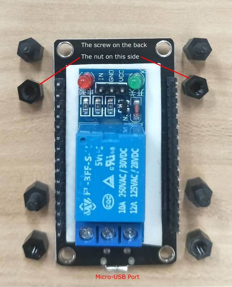
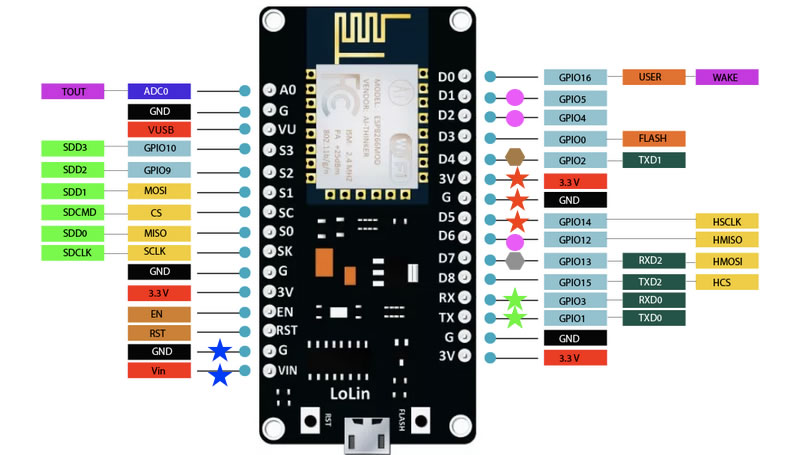
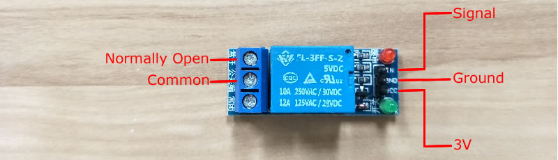
4.The NodeMCU and Relay
Attached the NodeMCU and Relay using a double side permanent tape. Pay attention to the orientation of the NodeMCU and the Relay.
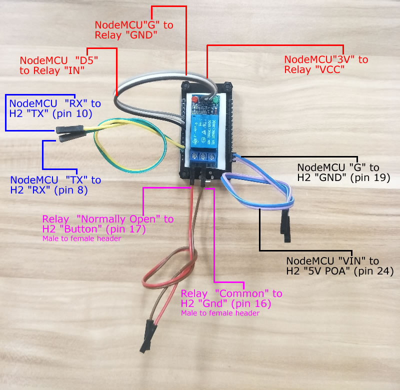
Plug in the header wires to the correct pins.
Mount the NodeMCU and Relay using two M3 screws
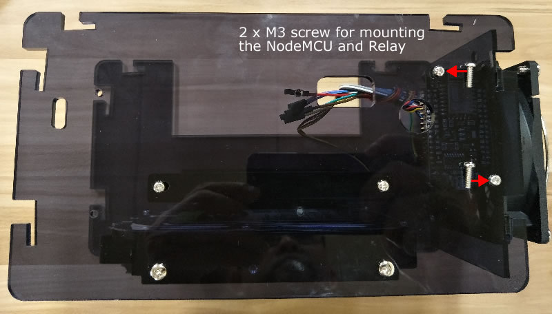
Pay attention the the NodeMCU orientation where the antenna of the NodeMCU is away from the 3.5" SSD bracket (top) and the Male to Female header wires connected to the Relay are close to the 3.5" SSD bracket.
5.Motherboard
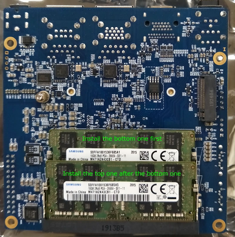
Install one RAM stick to the bottom memory bank first, before installing the another RAM stick to the top one. There is only one correct way to install them.
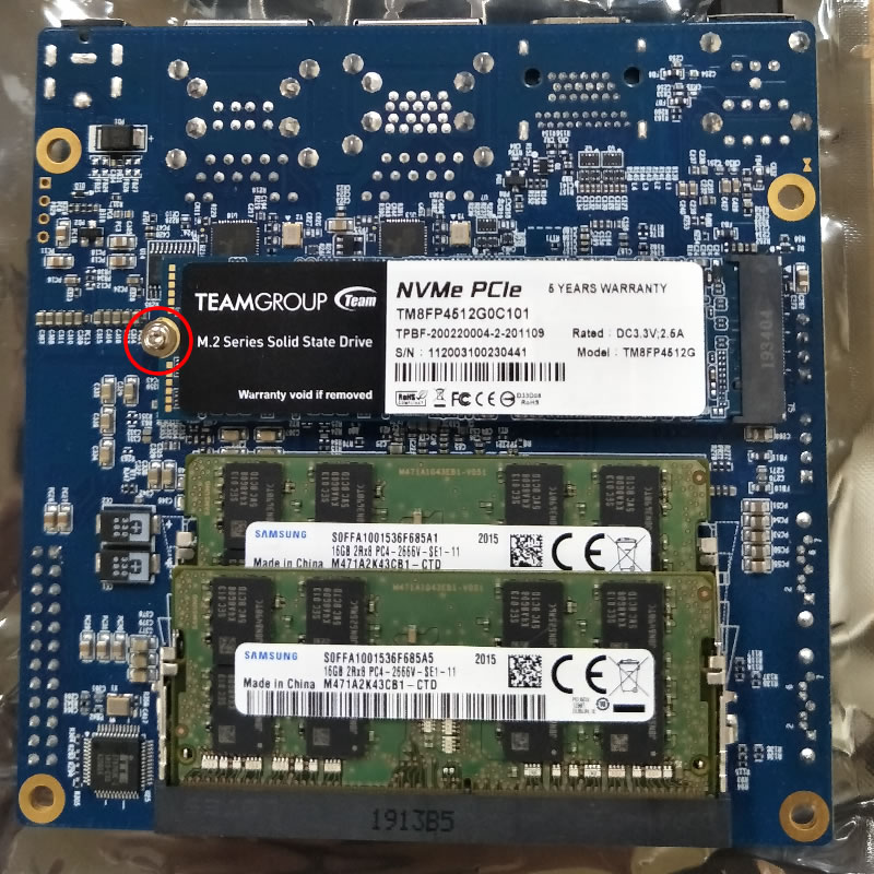
Remove the screw as pictured below before installing the NVMe. There is only one correct way to install it.
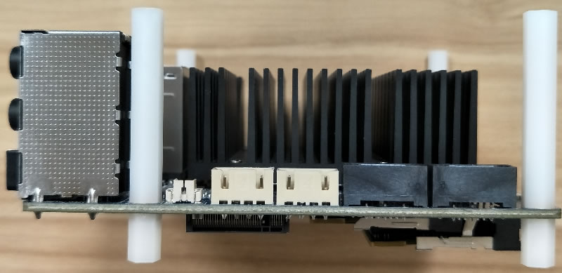
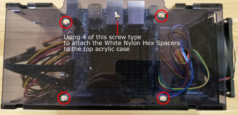
Install the White Nylon Hex Spacers and Screw Nut Stand-off
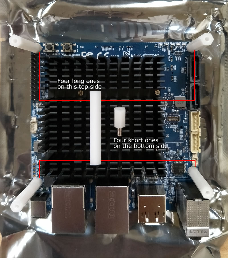
Tighten all the spacers and nuts.
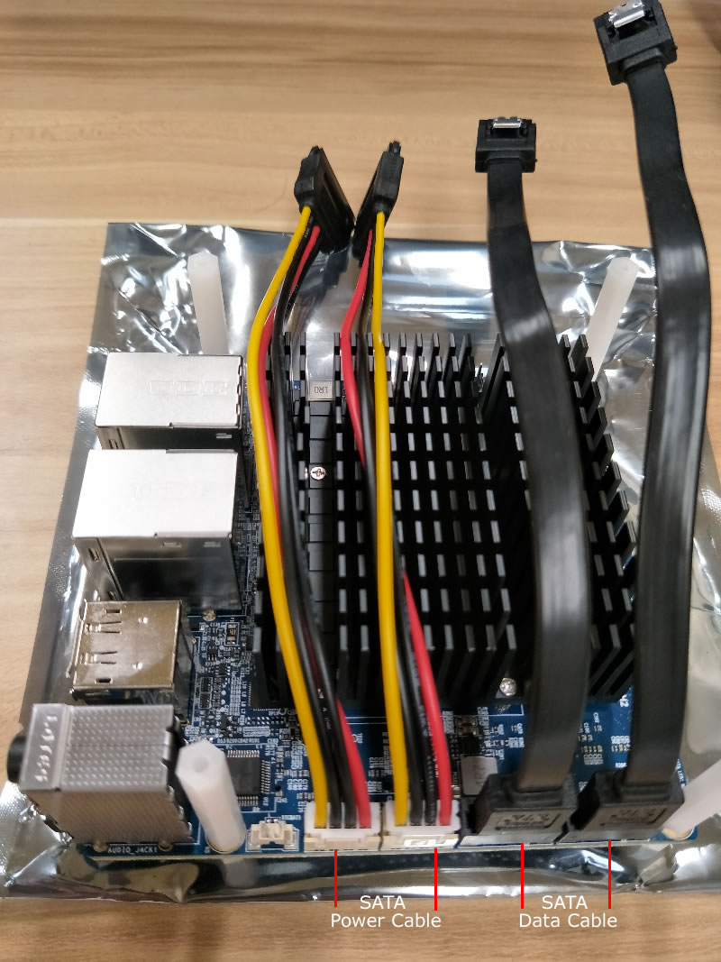
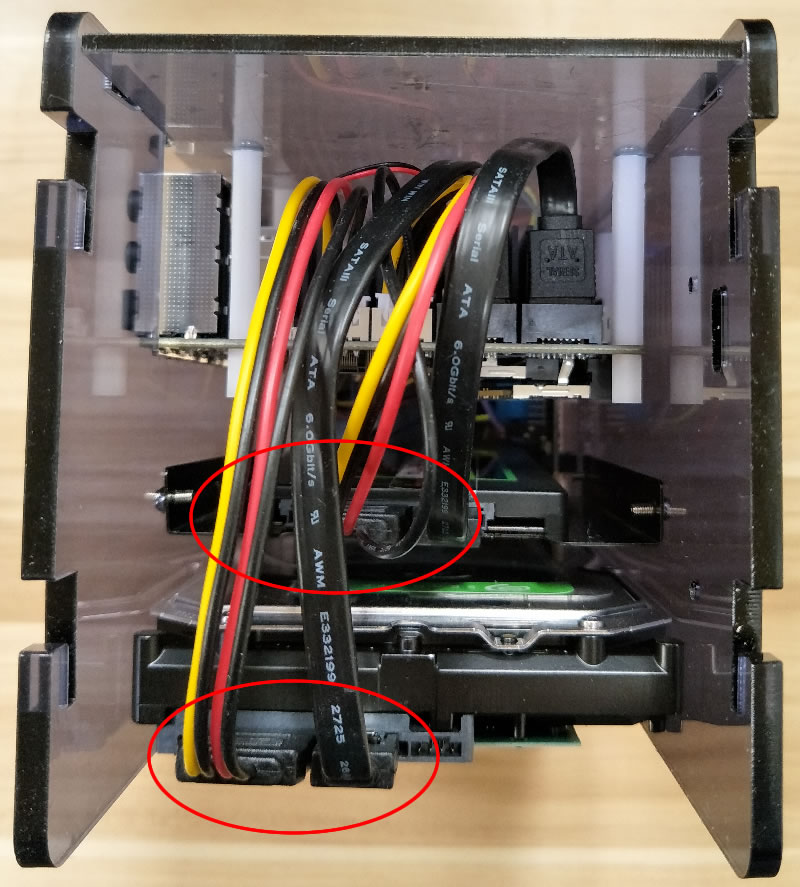
Plug in the SATA data and power cables. There is only one correct way to plug in both data and power cables.
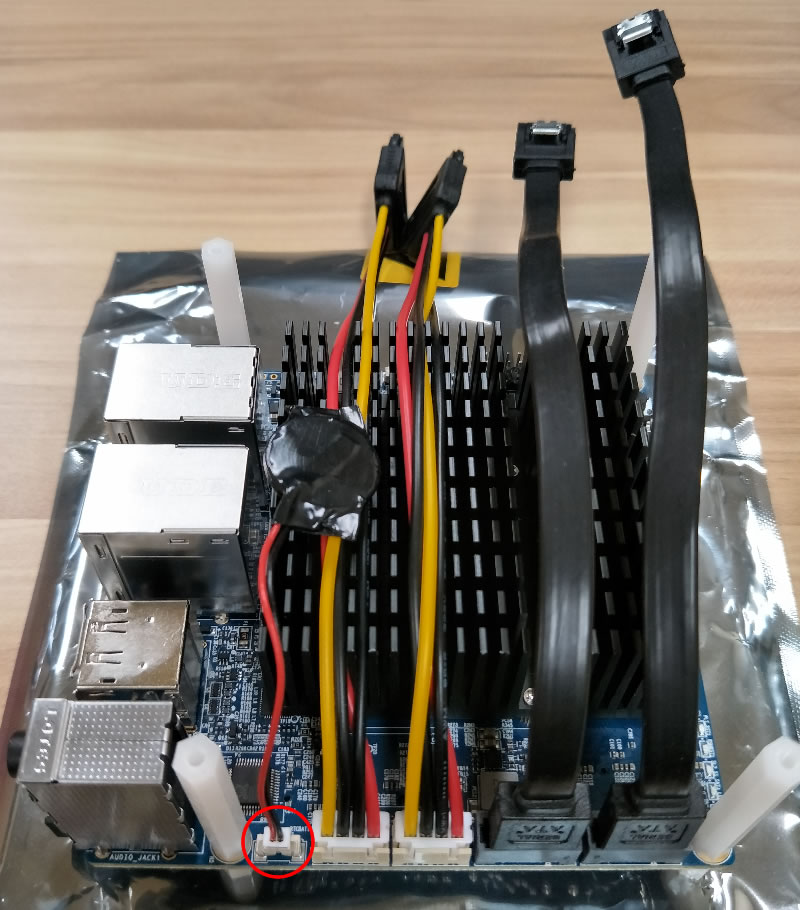
Plug in the RTC battery. There is only one correct way to plug it in.
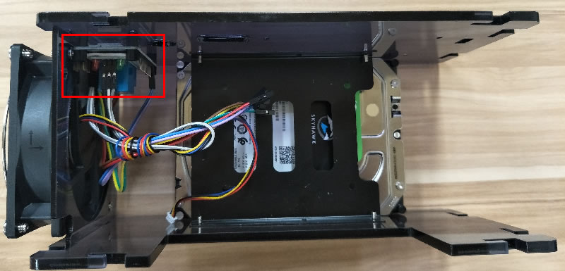
Connect 6 header pins on the motherboard to the NodeMCU and Relay
| H2 |
NodeMCU |
Relay |
Wire |
| pin24 (5v poa) |
VIN (blue star) |
|
female to female |
| pin19 (gnd) |
G (blue star) |
|
female to female |
| pin10 (uart1_tx) |
RX (green star) |
|
female to female |
| pin8 (uart1_rx) |
TX (green star) |
|
female to female |
|
3V (red star) |
vcc |
female to female |
|
G (red star) |
gnd |
female to female |
|
D5 - gpio14 (red star) |
signal (in) |
female to female |
| pin17 (button) |
|
normally open |
female to male |
| pin16 (gnd) |
|
common |
female to male |
The header pin outs on the motherboard.

The NodeMCU header pin outs.
The Relay header pin outs.
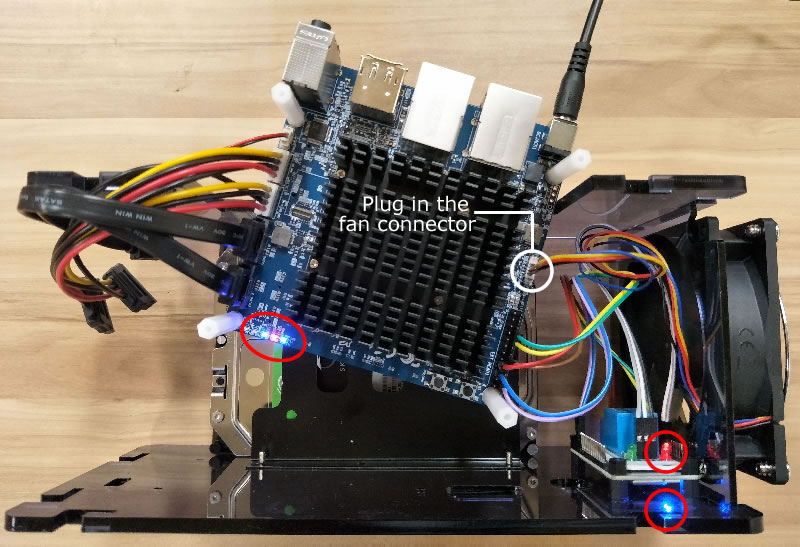
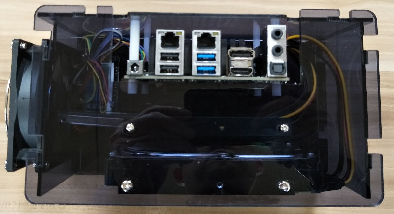
After connecting the header pins, plug in the fan connector to the fan socket on the motherboard. There is only one correct way of plugging the fan connector to the fan socket.
If the header pins wiring is correct, the leds on the Odroid motherboard, the NodeMCU and the Relay will be on.
Attach the top case using 4 screws. Remove the protective plastic coating before putting the screws in.
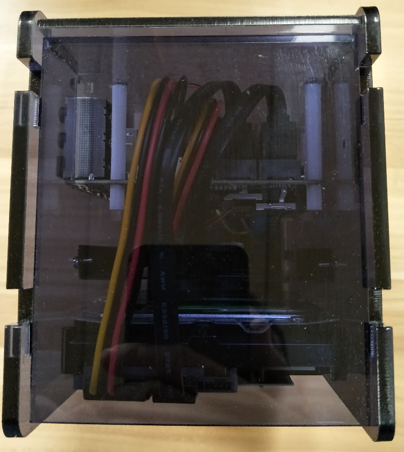
Attach the SATA Data and Power cables to the SSD (if installed) and the HDD.
Put the back cover by lifting the top cover a bit so the back cover can be slided in.
Congratulations! The Community Station is ready to be shipped out. Any question, please email support@oztell.com.
How to remotely control the power using NodeMCU
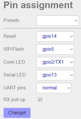
1.SET UP RESET PIN
DEFINE where power button wire is connected
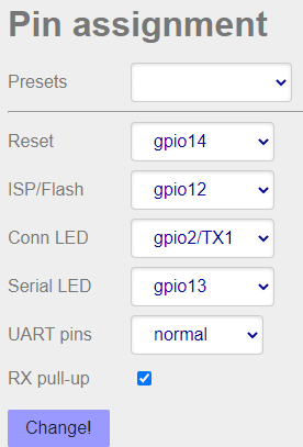
1.1 Go to "Home" page - change "Reset" to gpio14
1.2 Stay on Home page - click on "Change!"
2.GRACEFUL SHUTDOWN
SHORT power button press of 10ms
2.1 Go to "Home" page - change "ISP/Flash" to gpio12
2.2 Stay on "Home" page - click on "Change!"
2.3 Go to "uC Console" page - press Reset uC
3.HARD RESET
LONG power button press of any duration
Press button DOWN
3.1 Go to "Home" page - change "ISP/Flash" to gpio4
3.2 Stay on "Home" page - click on "Change!"
3.3 Go to "uC Console" page - press Reset uC
Wait for at least 4 seconds (some equipment need more
that 10 seconds).
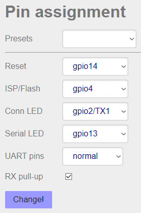
Release button UP
3.4 Go to "Home" page - change "ISP/Flash" to gpio5
3.5 Stay on "Home" page - click on "Change!"
3.6 Go to "uC Console" page - press "Reset uC"